The roller group is a core component of the belt conveyor, responsible for supporting the conveyor belt and reducing running resistance. Its assembly quality directly affects the stability, service life, and operating noise of the conveyor. The following details the key points of roller group assembly from four dimensions: pre-assembly preparation, core assembly process, to ensure a standardized and efficient assembly process.
1. Pre-Assembly Preparation: Lay the Foundation and Avoid Risks
Before assembly, three core tasks—"material inspection, tool preparation, and environment cleaning"—must be completed to avoid rework or quality hazards caused by preliminary omissions.
1.1 Material Counting and Quality Inspection
●Check the core components of the roller group one by one: rollers (including roller bodies, bearing housings, bearings, and oil seals), brackets, shafts, fasteners (bolts, nuts, washers), etc. Ensure the quantity matches the drawings, with no missing or wrong parts.
●Quality screening of key components:
◆Roller body: No bumps, deformation, or rust on the surface; uniform wall thickness (spot inspection with a caliper is available); the bearing housings at both ends are firmly welded (no false welding or cracks).
◆Bearings: Flexible rotation without jamming or abnormal noise; intact seal covers (to prevent dust and oil from entering); models match the drawings (e.g., deep groove ball bearings 6204, 6205).
◆Brackets: The material meets requirements (mostly Q235 steel); no burrs or deformation at the welding joints; accurate position of mounting holes (the hole diameter matches the bolts, with an error ≤ 0.5mm).
1.2 Tool and Auxiliary Material Preparation
●Essential tools: Torque wrench (critical for ensuring the bolt tightening torque meets standards), adjustable wrench, hexagon socket wrench, caliper (for measuring dimensions), feeler gauge (for measuring gaps), rubber hammer (to avoid damage to components from hard knocking), bearing installation tools (e.g., sleeve, press; direct knocking on the bearing inner ring is prohibited).
●Auxiliary materials: Grease (matching the bearings, such as lithium-based grease No. 2, used for bearing lubrication), rust inhibitor (sprayed on the welding joints of the brackets after assembly), cleaning cloth (for wiping oil stains and dust on components).
1.3 Assembly Environment Requirements
●The site should be flat and dry, avoiding humid environments (to prevent component rusting) and dusty environments (to prevent impurities from entering the bearings).
●Lay protective pads (e.g., rubber pads, wooden boards) to prevent scratches on the roller body caused by direct contact with the ground.
2. Core Assembly Process: Operate in Sequence and Ensure Precision
The assembly of the roller group should follow the sequence of "first assemble the roller unit → then assemble the bracket → finally fix and verify". Precision must be controlled in each step to avoid component misalignment.
Step 1: Roller Unit Assembly (the Core of the Core)
The roller unit is the "execution unit" of the roller group, composed of the roller body, bearings, shaft, and oil seal. During assembly, focus on ensuring "flexible bearings and reliable sealing".
1.1 Assembly of Bearings and Bearing Housings
First, apply a small amount of grease to the inner wall of the bearing housing (a thin layer covering the inner wall is sufficient; excessive grease may cause the bearing to heat up).
●Use a press to smoothly press the bearing into the bearing housing (the force application point is on the bearing outer ring; pressing the inner ring is prohibited). Ensure there is no gap between the bearing and the bearing housing (inspection with a feeler gauge is available, with a gap ≤ 0.05mm).
●Install the oil seal: Embed the oil seal (mostly double-lip oil seal) into the groove of the bearing housing. Ensure the oil seal is tightly attached to the bearing outer ring without deviation (to prevent grease leakage or dust entry during operation).
1.2 Assembly of Shaft and Roller Body
●Pass the shaft (with a smooth surface and no burrs) through the bearing inner ring at one end of the roller body, and gently push it to the bearing inner ring at the other end. Ensure the shaft is fully attached to the bearing inner ring (no looseness).
●Rotation test of the roller body: Rotate the roller body by hand; it should rotate flexibly without jamming or abnormal noise, and the rotation inertia should be uniform (no "stuttering feeling"). If there is jamming, disassemble and check whether the bearing is installed in reverse or if there are impurities.
Step 2: Assembly of Roller Unit and Bracket
The bracket is the "support frame" of the roller group. It is necessary to ensure the accurate position of the roller unit on the bracket to avoid deviation of the conveyor belt.
2.1 Positioning of the Roller Unit
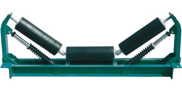
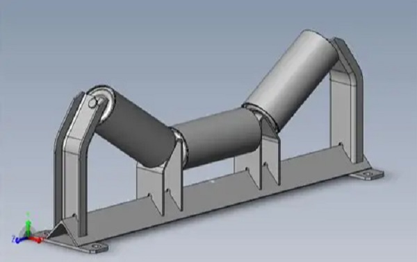
●According to the requirements of the drawings, place the assembled roller units (a single roller group usually contains 2-5 roller units; for example, a "parallel roller group" contains 3 units, and a "trough roller group" contains 2 side rollers + 1 middle roller) into the mounting grooves of the bracket.
●Special attention should be paid to the trough roller group: The angle between the side rollers and the middle roller (usually 30°, 35°, 45°, according to the drawing requirements) should be measured with an angle ruler, with an error ≤ 1° (angle deviation will cause uneven force on the conveyor belt, easily leading to deviation).
2.2 Bolt Fixing
●Pass the bolts through the mounting holes of the bracket and the bearing housing holes of the roller unit, put on the washers (flat washer + spring washer to prevent loosening), and first tighten the nuts by hand.
●Use a torque wrench to tighten the bolts according to the torque specified in the drawings (e.g., the torque for M10 bolts is usually 25-30N·m, and for M8 bolts is 15-20N·m). Excessive torque (which may cause bolt breakage) or insufficient torque (which may cause loosening during operation) is prohibited.
●Tightening sequence: Tighten symmetrically (e.g., 4 bolts should be tightened in a "diagonal sequence" to avoid bracket deformation).
Step 3: Overall Verification and Adjustment
After assembly, conduct an overall inspection to correct deviations in a timely manner:
●Use a level to detect the bottom surface of the bracket: Ensure the bracket is horizontal (horizontal deviation ≤ 0.5mm/m). If it is inclined, adjust the gaskets (place gaskets at the bottom of the bracket; forced bending of the bracket is prohibited).
●Check the parallelism of the roller units: The side rollers of the trough roller group should be symmetrically distributed on both sides of the middle roller, with a parallelism error ≤ 0.3mm/m (detection by the rope-pulling method: pull a straight line at both ends of the rollers and measure the distance difference between the rollers and the straight line).
●Rotate all rollers again: Ensure all rollers rotate flexibly without "individual jamming". If there is jamming, disassemble and check the assembly of the bearings or shafts.