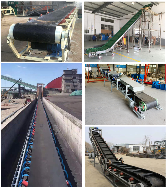
In the design of the drive device, couplings are mostly used, and here is a brief introduction to them: couplings are commonly used components in mechanical transmission. It is used to connect the two shafts, and the two shafts cannot be separated when the machine is running; Only after the machine has been stopped and the coupling has been disassembled can the two axes be separated.
The two shafts connected by the coupling often cannot ensure strict alignment due to manufacturing and installation errors, deformation after load-bearing and the influence of temperature changes, but there is a certain degree of relative displacement. This requires that when designing the coupling, a variety of different measures should be taken from the structure to make it have the performance of adapting to a certain range of relative displacement.

According to whether there is the ability to compensate for various relative displacements (that is, whether the connection can be maintained under the condition of relative displacement), couplings can be divided into two categories: rigid couplings (without compensation ability) and flexible couplings (with compensation ability). Flexible couplings can be divided into two categories: flexible couplings with inelastic elements and flexible couplings with elastic elements.
Rigid couplings
This type of coupling is sleeve type, clamp type and flange type. The flange coupling is a combination of two flanged half couplings to transmit motion and torque. The flange coupling can be made of grey cast iron or carbon steel, and cast steel or carbon steel should be used for heavy loads or when the circumferential speed is greater than 30m/s. Because the flange coupling is a rigid coupling, it lacks the ability to compensate for the relative displacement of the two axes, so the requirements for the neutrality of the two axes are very high. When there is a relative displacement of the two axes, it will cause additional load in the machine, which will worsen the working situation, which is its main disadvantage. However, due to the simple structure, low cost, and large torque transmission, it is often used when the speed is low, there is no impact, the rigidity of the shaft is large, and the centering is good
Flexible couplings
(1) Flexible coupling without elastic elements
Due to their flexibility, these couplings compensate for the relative displacement of the two axes. However, because there are no elastic elements, it cannot cushion and dampen vibrations. The following are commonly used:1) Cross slider coupling
The cross slide coupling consists of two semi-couplings with grooves on the end face and an intermediate disc with teeth on both sides. Since the teeth can slide in the groove, the relative displacement between the two axes can be compensated for during installation and operation. The material of this coupling part can be made of 45 steel, and the working surface must be heat treated to improve its hardness; Q275 steel can also be used for lower requirements without heat treatment. In order to reduce friction and damage, oil should be injected from the oil hole of the intermediate disc for lubrication
Because the semi-coupling and the middle disc form a moving pair, the relative rotation cannot occur, so the angular velocity of the driving shaft and the driven shaft should be equal. However, when working with relative displacement between the two shafts, the intermediate disc will generate a large centrifugal force, thereby increasing the dynamic load and wear. Therefore, it should be noted that the working speed should not be greater than the specified value.
2) Slider coupling
This coupling is similar to the cross slide coupling, except that the grooves on the two sides of the half coupling are wide, and the original middle disc is changed to a square slide without teeth on both sides, and is usually made of cloth bakelite. Due to the reduced mass of the intermediate slide, it has a high limit speed. The middle slider can also be made of nylon 6 and formulated with a small amount of graphite or molybdenum disulfide so that it can be self-lubricated when used. This coupling has a simple structure and compact size, and is suitable for small power, high speed without severe impact. According to the selection of various parameters, the coupling selected in this design is a cross slide coupling. The cross slider coupling is a coupling that uses the middle slider to slide in the corresponding radial groove on the end face of the half coupling on both sides to realize the connection of the two halves of the coupling. It consists of two half-couplings with grooves on the end face and an intermediate disc with teeth on both sides. Since the teeth can slide in the groove, the relative displacement between the two axes can be compensated for during installation and operation. The cross slider coupling is often used in general motors, generally used for transmission at a speed of 250rmin, the stiffness of the shaft is large, and there is no violent impact. A belt conveyor that conforms to the design of this article.